Once upon a time, I bought some 13 pin DINs to wire my own cables for the Icom 706 (and also later radios). 13 pin solder cups, with my clumsy hands. right. great idea.
Icom supplies the radios with a pigtail connector – so they realize it’s a crappy connector. There’s the splitter cables, and other options, but that requires a lot of buying and planning ahead. I do like this product but, being the cheapskate I am, I don’t want to spend $79 on it right now. This is another option – a real simple breakout that the user can wire their own outputs for… BOTH options require a 13 pin to 13 pin DIN cable that I just don’t have.
I happened to look at my collection of parts – and I noticed that I had some DB9, DB15, and DB25 connectors on the shelf. Bob, K5BG, was generous enough to give me one of his 13 pin DIN breakout pigtails. I grabbed a matching set of connectors and got to work.
I had considered putting an EMI spin on the connector, and trying to put some grounds in place to protect signals, but in this case, I don’t think it’s warranted for this application. I went simple, and wired it pin-for-pin, keeping the same numbering. I also wired up EVERY pin, so this contraption is useable no matter what Icom radio I connect it to. Below is the basic pinout illustrated using excel. I’m too lazy to do a nice pretty diagram in Visio.
I put the female connector on the radio, because it’s a good practice to not have exposed pins on the source connector like this.
For proof of concept, I soldered an RCA panel mount jack to pins 2 and 3 of a DB-15 male, and connected my foot switch (after the Heil headset mod, that’s what started all of this), and the radio keyed as I wanted. I’m getting closer to ready for sweeps.
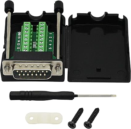
This is not where the project stops, yet. I want to set this up for amplifier connections, and possibly other interfaces – at least this is a connector I can solder to. Additionally, breakout boards aren’t as expensive, and don’t require that I find 13 pin DIN cables. Here’s one example
I still need to get some DB15 hoods, but an extended hood like the one shown above would be great, as I could even put my PTT foot switch RCA connector in the hood, and then run cables off to the amp or whatever I’m working with. Soon enough I’ll look back at what interconnects I need for the PW1, once I get power run for it.
19 July 2024 Update:
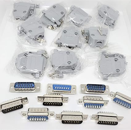
Ordered the hoods and connectors from Amazon – it was cheaper than just buying one hood.
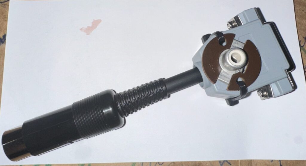
I drilled a hole in the hood, and pulled PTT and ground leads through it to add an RCA jack for my PTT connector. While digging through my box of connectors, I found a panel mount jack with mounting holes exactly the same spacing as my DB15 hood.
I clipped the center conductor on the back of the RCA jack to the shortest I could get it, and then soldered those leads to the RCA, and put it all together. This gives me a permanent PTT connection on the dongle, so I don’t need to have other plugs and connections when using that function ONLY.
Unfortunately, I don’t have screws long enough (and the proper diameter) to go through the entire hood AND the RCA jack flange, so I used a couple ty-wraps. It looks a bit janky – but way less so than the test-connector I built with just an RCA jack soldered to the pin field of a male DB15 with no hood… it looked really sketchy (but it worked).
The next cable to build will be a DB-15 to the 7 pin ACC connector for the PW-1, but I don’t need that YET. I have another cable that was solely a 13 pin DIN to 7 pin ACC connector – I’ll likely cut off the 13 pin connector (my original pigtail) and salvage that 7 pin cable for this function….
To simplify the overall cable mess behind my desk, I am considering wiring pins 14 and 15 to be CI-V pins… shield on 14 and center conductor on 15. I could then route the single cable off to where my amplifier is, and have the CI-V and 7 pin DIN connectors break out of the cable at the far end. The challenge there is just finding cables with enough conductors.


