So another mobile install, and more worries about how much space I have for wire….. things are always tight. I’ve been trying to plan this one out a bit, and started looking for ampacity charts. For the most part, they agree, but there’s always that question of “chassis wiring” versus whatever the other category is.
Then i started thinking about some of the airborne systems I’ve worked on in the past. It’s no secret that I’ve spent a lot of time in MIL-STD-461 for EMI….but I digress. I started to question whether or not I REALLY needed 16 gauge wire for a dash camera or a CB that doesn’t transmit more than 4W of RF power anyway….. and really, the answer is “no”.
But while I KNEW this to be the case, where could I go for real guidance? I knew I didn’t need to pull 8 gauge wire for my Motorola radio – heck, they don’t even SHIP it with wire that big. And i certainly didn’t need 14 gauge wire for a 7A current draw that my 50W amateur radio COULD draw in a maximum power worst case configuration.
So I had to change by “rule of thumb” approach of just using 14 gauge wire when all else failed. It was time to take a more measured approach. So here it goes:
Prior to detail planning, it’s important to note that I’m putting a breaker / fuse panel in the front cabin, and one in the back. Since most of todays radio equipment has remote-head capability, the distance from the power panel to the radio has to be considered, as well. I prefer to make drawings, though in this case, I really did more table-based planning…
Step 1 was to identify my loads, and put them in a list, along with some other pertinent data.
| Device | Current Draw (max) | Length from fuse panel |
| CB | 3A | 4 feet |
| Ham Radio (dual band) | 7A | 10 feet |
| Motorola Radio (100W) | 20A | 5 feet |
| Dash cam | 500 mA | 10 feet |
| Computer charger | 1.2A | 4 feet |
| Light Control Circuit | 100 mA | 15 feet |
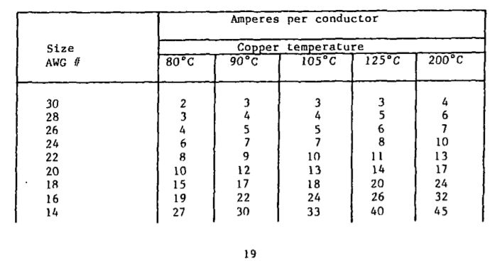
Now, I could go about calculating resistance, and other such things, but there comes a point when you go to a document for what you need. In this case, I stumbled on MIL-STD-339 (replaced by MIL-HDBK-508).
Assuming reasonable lengths, the standard not only provides current ratings, but also accounts for deratings for temperature and number of cables in a bundle. Now, that being said – my little install is not the combat or tactical vehicle that the standard is written for – but also consider that the reliability needed for those environments far exceeds what is needed for my application. Moreover, a vehicle like that is purely utility, so they don’t have SPACE to allow for overkill when it isn’t absolutely necessary.
Now, step 2 (the harder part, but not too hard) is to compare the current draws in the first table to the standard, and to determine what the MINIMUM gauge wire I will need is.
Going to the standard, table IV presents the base information needed:

Now, this is the BASE information – subsequent tables present derating for the number of cables in a bundle (Which adds to heating, thus derating cable current) and ambient temperature correction over 30 degrees C – for most applications, this is beyond what civilians will run into, though some folks in places like AZ and NM might run into that…
| Device | Current Draw | Length | Minimum Wire Gauge | Notes |
| CB | 3A | 4 feet | AWG 28 | |
| Ham Radio (dual band) | 7A | 10 feet | AWG 20 | |
| Motorola Radio (100W) | 20A | 5 feet | AWG !4 | |
| Dash Cam | 500 mA | 10 feet | AWG 30 | |
| Computer Charger | 1.2A | 4 feet | AWG 30 | |
| Light Controller | 100 mA | 15 feet | AWG 30 |
Now, let’s face it – I’m not a major manufacturer with a wire crib, so I’m going to pair things down a bit, and pick a couple different gauges and allow for some overkill where it makes sense. Based on the table above, I would pick AWG 18 zip cord for my smaller loads (under 10A), AWG 14 for the heavier loads (100W radio), and then I’ll still probably run AWG10 for my main panel feeds.
Now, all that said – I would use the handbook guidance as-is for lengths less than 10 or 15 feet. Once the cable length starts exceeding that, it’s probably time to up your AWG. The standard does provide for a calculation of resistance over distance – in that case, it’s up to the user to determine if their equipment can handle a lower voltage… you’ll never have alternator 14V at your load equipment… and in most cases, the slight upsizing done for convenience of wire selection will reduce cable resistance to an acceptable level. For some of todays more sensitive HF equipment, for example, the radio will derate output power if the input voltage drops – so that needs to be considered. Since the resistance is a function of current draw, running a 100W radio on a AWG 20 wire will work fine for receive, but when the radio is keyed up, the voltage will drop dramatically across the wire, and the radio will likely power down, if the wire doesn’t become a fuse first.
Another complication, as my buddy Mark pointed out, is the possibility that the source is less then ideal – such as an alternator under heavy load, or a weakened battery without the engine running. In these cases, some equipment will just fold back power output – and that’s the best case scenario. Some equipment will draw more current when the voltage is lower, in an attempt to source enough total energy to operate at full output. These cases are even worse, because it adds additional load capacity that must be planned for. Generally, however, this type of equipment is not a simple resistive load, and will have some degree of low voltage shutoff… but that’s another possibility that should be part of your planning – thus the reason for breakers and fuses that are appropriately sized. In my case, i put a “oh crap” 50A resetting breaker under the hood, and then 30A breakers front and back, followed by appropriately sized breakers for each piece of equipment.
I guess the takeaway there is that the standard provides some good guidance as a starting point, to avoid overkill that will limit installation options, the user DOES have to account for equipment limitations, as well… well, that, and make sure you follow guidance from the equipment manufacturer when you have it. Then make sure you have proper circuit protection….
