I love the Icom 7300 – it has a TON of features. One of the intriguing features is the voice keyer – the radio has 8 memory slots, four of which are potentially accessible via hardware buttons connected to the microphone jack (using resistors).
The rear panel has a very dense (13 pin DIN) accessory jack which can be used to interface to an amplifier, among other things.
In the past, I’ve used ACC jacks like that for footswitch PTT activation when I’m using a boom or headset microphone. It’s probably NOT wise to tap into this line to try and run PTT on the amp and radio, but rather to use the mic jack PTT line, and let the radio handle timing and signals to the amplifier to keep the amp healthy and happy (an Icom PW1)…
so, I could build a more complex octopus cable for the mic jack. I’ve had headsets plugged into the backs of radios, fronts of radios, headphone splitters that were tied to the radio… all possibilities (see my post about the Behringer headphone distribution amp).
Instead, I decided to build some sort of interface box.
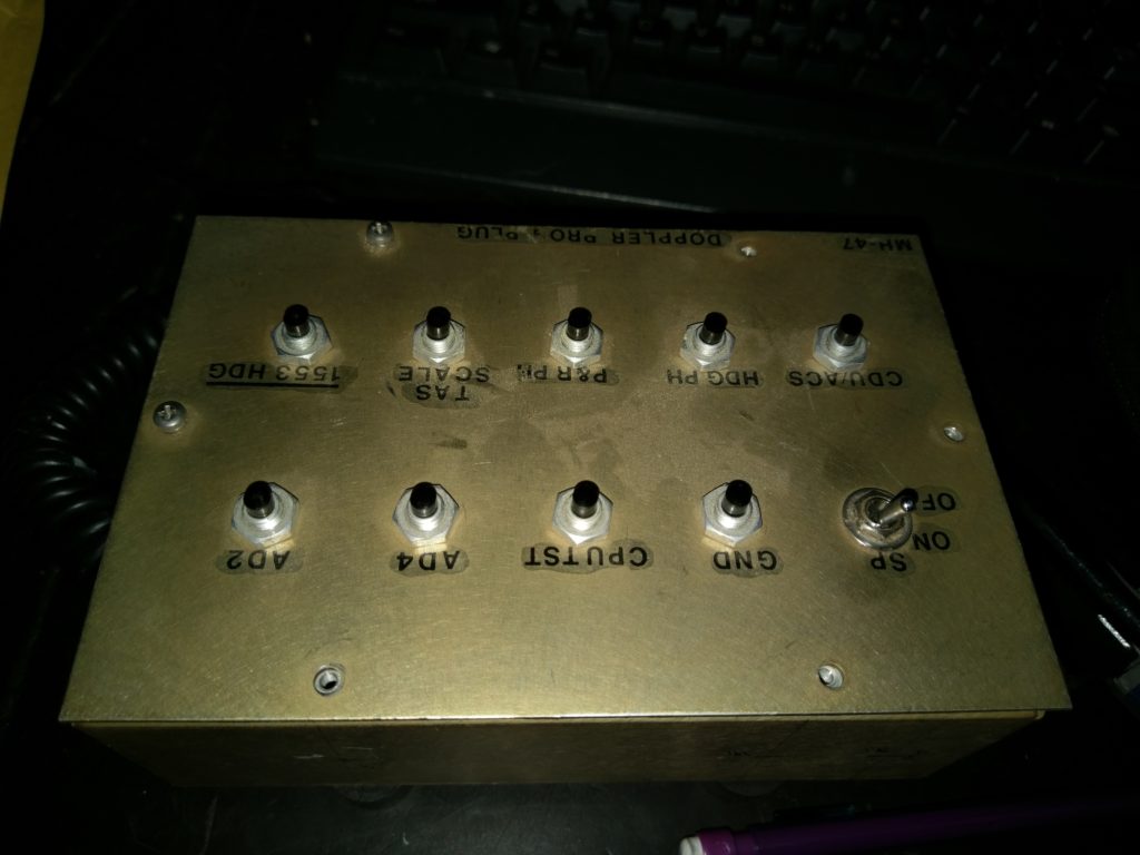
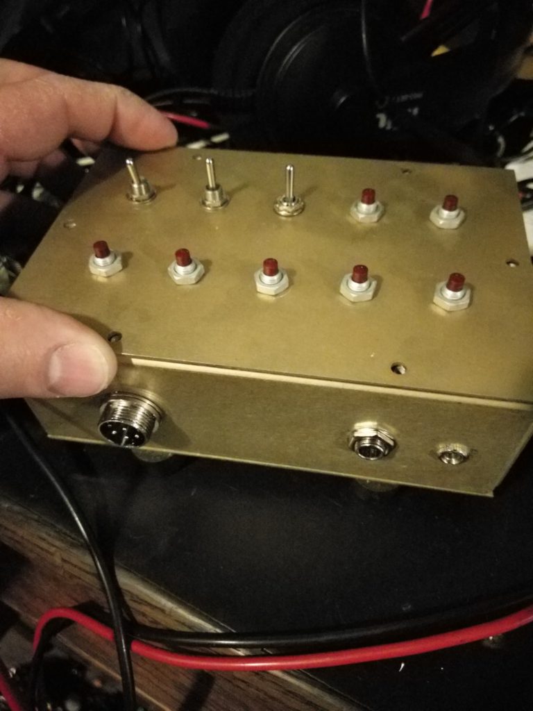
I just so happened to have picked up a project box at an estate sale with 9 pushbutton momentary switches and one toggle on it, with a cable gland on one end.
https://www.qsl.net/on7eq/projects/arduino_icom_keyer.htm (among other links) shows how a series of resistors can be used to access the top 4 voice memories (or CW, if in that mode, i believe).
What was I going to do with the remaining 5 switches, though?
well…. a push-to-talk button is a good start, for testing, or just quick operation. Now I’m down to repurposing 4.
A little research will show that the same lines that control the voice keyer will also stimulate the “up” and “down” functions that the microphone has on top of it for manual tuning. These seemed like a good use for 2 more of the switches.
Since this box was a “multi-use” box, i had several REQUIRED interface features in mind (I’ll get back to the buttons in a minute).
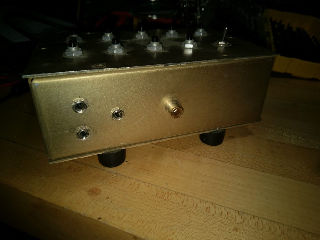
- RCA jack on the back for PTT (convenient plug on my footswitch)
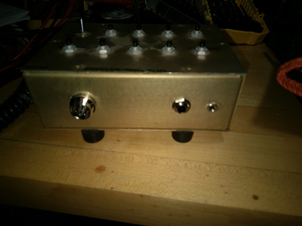
- 1/4″ stereo jack on the front for audio
- 1/8″ mono jack on the front for microphone input
Then I came up with a whole host of “nice-to-haves”:
- 1/8″ mono mic jack on the back for my boom microphone input
- 8 pin mic jack, so i can use a hand- or desk- mic without removing the box
- audio output on the back (1/8″) to go to my behringer input
- audio input on the back (1/8″) to feed my headset from one of the outputs on the behringer
- microphone jack selection (only one would be active at a time to limit ambient noise pickup)
- headset audio selection – to bypass the behringer box, if i wanted
- PTT inhibit – just because sometimes it’s necessary?
Honestly – all of those things were EASY to implement.
For mic jack selection, I put an ON-OFF-ON SPDT micro-toggle in place of one of the existing pushbuttons.
For PTT inhibit, I re-purposed the existing ON-ON SPDT toggle (and left one side disconnected).
For the Behringer interfacing, I put two 1/8″ jacks on the back:
One as an output, and one (input) wired in parallel with the headset 1/4″ jack. A toggle (ON-OFF-ON, SPDT) takes receive audio from the 8 pin jack, and either drives the front panel jack directly, or drives the 1/8″ ‘output’ jack on the rear panel. The main idea here is that, when I want to use the Behringer to drive both headset and speakers, audio would route out the back, through the HA400, and then back in, to drive the headphones. Alternatively, an audio processor or DSP could be put in this loop, as well, though I don’t feel it’s necessary with the 7300’s internal DSPs at the moment.
One item of note – while all of the speaker connections are stereo, there is only a single output wire in the 8 pin connector. The front panel headset jack on the radio is also stereo – but if one reviews the service manual, it can be seen that the ring and tip (left/right channels) are just wired in parallel). For this reason, all of the audio jacks have ring and tip tied together. this is why I can use a single pole switch to switch audio between the different jacks.
So… as you can see, 3 toggles and 7 pushbuttons uses the 10 holes on the top panel. The interfaces I wanted were all fairly easy, and the device is a mild success.
Next, it was an issue of keeping buttons straight – I could have just scribbled on it with a sharpie, but that wouldn’t have looked very nice, when I did try to keep things neatly put together. Enter visio! once I got all the buttons and switches measured, and laid out black (cutout) circles where those would go, the rest was just labels and decoration.
I decided that I was only going to put a label on one surface – the top. This meant I also needed to put markings on the label to illustrate what the other various connectors were used for.

Once I had the label designed, I made a test-run on regular paper. I cut out the holes, and made sure everything lined up correctly – there were a few slight adjustments, but overall it worked well. Next, I sent it to the local Staples/OfficeMax print shop to be printed as a self adhesive label. If you do this, make SURE you check the box that this is NOT to be “scaled to fit” when printing. This almost caused big issues (and check it before you leave the store). Scale to fit will add margins to the page, and effectively shrink your print! Once I got the full label, i cut out the black circles (again) and it fit perfectly – so now I have a well labeled control box.
One final note – you may notice that the memory keyer switches are backwards from the normal expected order – this was a result of the simplest wiring under the back panel that i could fit. As long as you map the recordings appropriately, it’s not too bad to work with. If I had used more wire inside the box, it would have looked a little more complex, and that may have been resolved… but it works for me.


