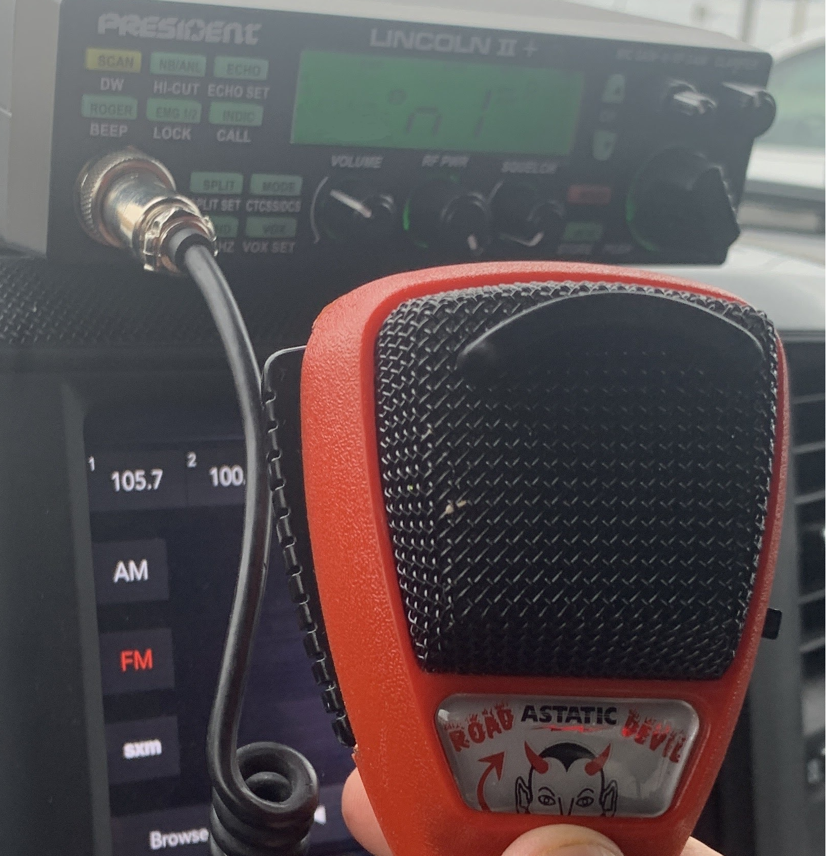
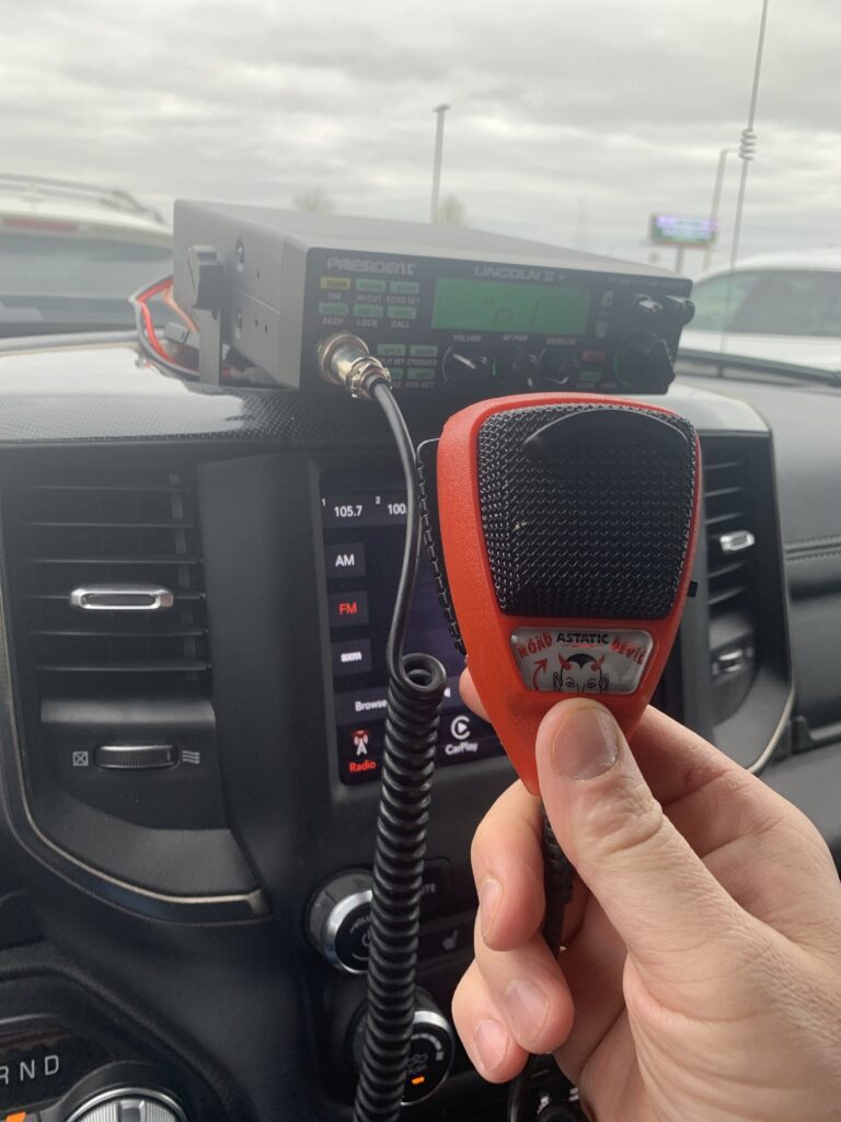
With the sunspot cycle coming to a point of good higher frequency propagation, I put a 10 meter radio in the car. Why not? The President Lincoln II+ has some features that most won’t want in a ham radio (echo? Roger beep?), but it’s decently priced, and has a nice size for applications like mine.
To that end, I decided I wanted a power microphone on it, just to provide a little more audio boost in a tailored manner – the Astatic Road Devil is, essentially, a D104 in a handheld package, as far as I can tell. Moreover, the mic has some noise cancelling capabilities, which are nice if you’re using it mobile.
One issue I had with the RD104 is the cord was a bit shorter than I liked, and it wasn’t wired for the president (I bought the 4 pin version, and the Lincoln II+ is a 6 pin radio).
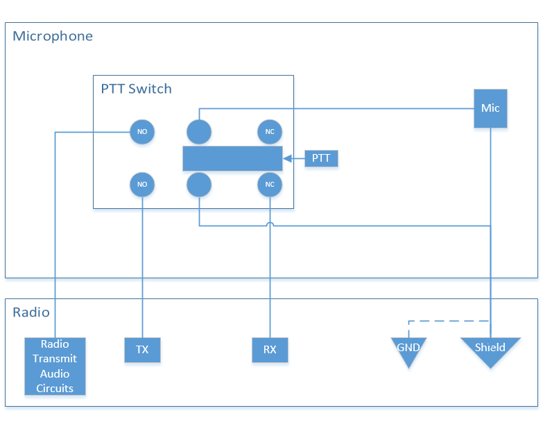
I carefully rang out the wires on the original mic (Shield-Audio-Transmit-Receive…. Typical cobra mic wiring for a CB mic), and found that the mic was wired as follows:
- 1: Shield: shield
- 2: Audio: White
- 3: Transmit: Red
- 4: Receive: Black
The way these things generally work (for a CB) is that the switch (DPDT) in the mic will switch ground or shield between the receive (normally closed) line and transmit (normally open) line. Most CBs won’t receive unless you short the receive pin to ground. SOME will break the audio line from the microphone, as well, but that’s not a requirement.

The president is no exception…. So I had to do some research to figure out the wiring on the 6 pin connector on the radio, and found the following:
- 1: Audio
- 2: Receive
- 3: Transmit
- 4: Up/Down (connected to either 12V or ground through a resistor of some specific value)
- 5: Shield
- 6: 12V Power
So changing a mic plug would have been easy… but I wanted a longer cord. Since I had a longer cord with a 6 pin plug on it from another radio, I opted to swap cords. When I opened the RD104, I was pleasantly greeted with the PCB inside containing labels for the different color wires.
Y, R, BL, BK, W, S
Typically, the stock configuration (for the cobra) ties Blue (common) and Shield together.
The corresponding functions for the colors on the PCB are as follows:
- Y (Yellow): Receive Ground (typically not used)
- R (Red): Transmit
- BL (Blue): Common (Circuit Ground, for switching)
- BK (Black): Receive
- W (white): Audio
- S (Shield): Shield ( Audio Ground)
Note that in sticking with good design, Astatic did NOT use the audio shield/return as the circuit ground – they are kept separate. This is important later.
After figuring out which wires went to what functions (except yellow), I removed the old cord and desoldered it from the PCB.
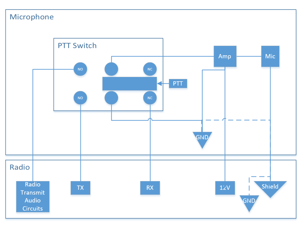
Once I rang out my new mic cord, and knew which wires went to which pins, I commenced to wiring the mic. I got everything connected, and just as I was about to connect the 9V battery, I had a stroke of genius. I had seen a youtube video where one of the “Custom CB shops” did the “battery eliminator mod” for a Lincoln II+ / RD104 combo. I could find NOTHING on the internet about it. I DID, however, notice that the mic amp is a simple 2 transistor amplifier with some frequency response shaping. This means there’s nothing magical about 9V from the battery – as a matter of fact, it explains why the gain drops when the battery gets weak!
So I took the wire from pin 6 of the cable, cut the red wire from the 9V battery snap, and connected the power wire from the radio to the 9V line inside the mic. I could possibly have used a small dropping resistor to limit the gain, but decided this wasn’t necessary for my application.

I took the mic outside, put it on the radio, keyed it up, and… nothing. No PTT. Why not…. I was worried i got the wiring wrong somehow.
Then I had an epiphone…. Remember the shield / circuit ground thing? Yeah…. I left BL on the PCB disconnected, assuming the shield would have been tied to circuit ground inside the mic… nope!
I then put a short jumper between BL and S on the PCB…. Keyed the mic (gain maxed on the radio and pretty high on the mic), and was greeted with a horrific noise… feedback. Since I had “Monitor” on (“talkback” for the CB crowd), the sensitive mic was picking up the monitor audio and causing feedback. I turned the radio gain AND RD104 level down to about 50%, and heard crisp, clear audio on the other end! Success! One remaining task is to check my audio levels and come up with a working set of gain values using a remote receiver to verify audio quality. For now, turning it up to a level below the feedback level is a good start.
As a closing note, this will work for most radios with power at the mic jack… President, Icom, Yaesu, Kenwood…. just be mindful of the current limits and actual voltages. 8V will work (Yaesu, i believe), but there could be some loss of gain. Too much current draw could damage the regulator if this point isn’t tied directly to the 12V input supply. Use at your own risk….

