I’ve been an electromagnetic interference (EMI) engineer for… well… a bunch of years at this point. As such, I’ve learned a lot about how to tackle problems, and how to solve the underlying issues. That said, I’ve seen a lot of different forums and message boards (unrelated to EMI, RFI or EMC) where people have issues, and just blindly slap some ferrite on it – whatever ferrite they scavenged from old computer monitor cables – without understanding what’s really going on. It drives me crazy. This isn’t to say that a ferrite can’t be the right answer in some cases – I’ve used a few to solve problems – but oftentimes it’s either not the right answer to totally fix a problem, or it’s poorly executed.
Now- don’t get me wrong. I DON’T expect everyone to understand the world of EMI… but many of the guys asking these questions are “technical” folks (hams). I do think the amateur community (FCC and ARRL) would do well to add a few BASIC questions to the pool regarding interference – beyond who has to resolve it if there’s an issue.
Where am I going with this? Well… I’ll discuss a few high level ideas, and put in a couple links. There’s NO value in me reinventing the wheel.

The above image is pretty common in the EMI world – if all three of the components exist, there’s a problem. If you can remove the coupling path, limit the energy the source is putting out, or harden the victim, you remove that leg, and the whole thing falls apart.
This page has a decent introduction on the first page – after that, it gets into standards, which goes a bit beyond what the novice needs. Texas Instruments also has a video on the subject.
Now – one thing that I’m sure some of the introductions discuss (they might, but admittedly, I haven’t searched through all of them) is that the scale of the source/victim systems will affect how one can resolve the issue. If the source and victim are, for example, your neighbors 1500 watt transmitter causing our TV to lose reception or be damaged, the approach and solution will be different than if it’s an interaction between a noisy switching power supply causing additional noise on your shortwave receiver that is powered from that supply.
That being said – sometimes, the same approaches can solve multiple level issues. I used the same approach to fix a noisy diesel generator cart that I used in system designs for radio installs described here on my blog with great success. This approach was also discussed by Bob Lee, W0GXA, in August 2016 here. Is wire twisting (my approach) a magic bullet?
Nope.
It just so happens to have been a good approach to 2 or 3 issues. For the generator and air conditioners, twisting a wire pair better coupled the noise source to it’s associated return, thus keeping it from leaving the system. It resolved the path by keeping the noise inside the source system. In some ways, it reduced the severity of the source, as well – the path was still present, since the issue was a radiated issue. I’ve been involved in some system designs that had to withstand VERY high fields – the same approach is used to harden the potential victim – wire twist helps reduce differential mode noise – noise between the high and return lines – thus clipping the victim leg of the triangle, and resolving the issue.
Now… do ferrites have a place? yup. I had to apply one in my truck to my phone cable. I had an issue where my radio would key up (50W, VHF) and cause carplay to disconnect my iphone. An apple lightning cable is (in theory) a shielded USB Cable – there’s not a whole lot that can be done if that’s the susceptible portion of the victim. I can’t twist wires, or add capacitors, so it was a bit of a “Hail Mary” to clip on a ferrite – but it worked. I should have researched the mix, and chosen one specifically for VHF frequencies…
That said – I see folks snapping them on all sorts of cables, whether they’re needed or not.

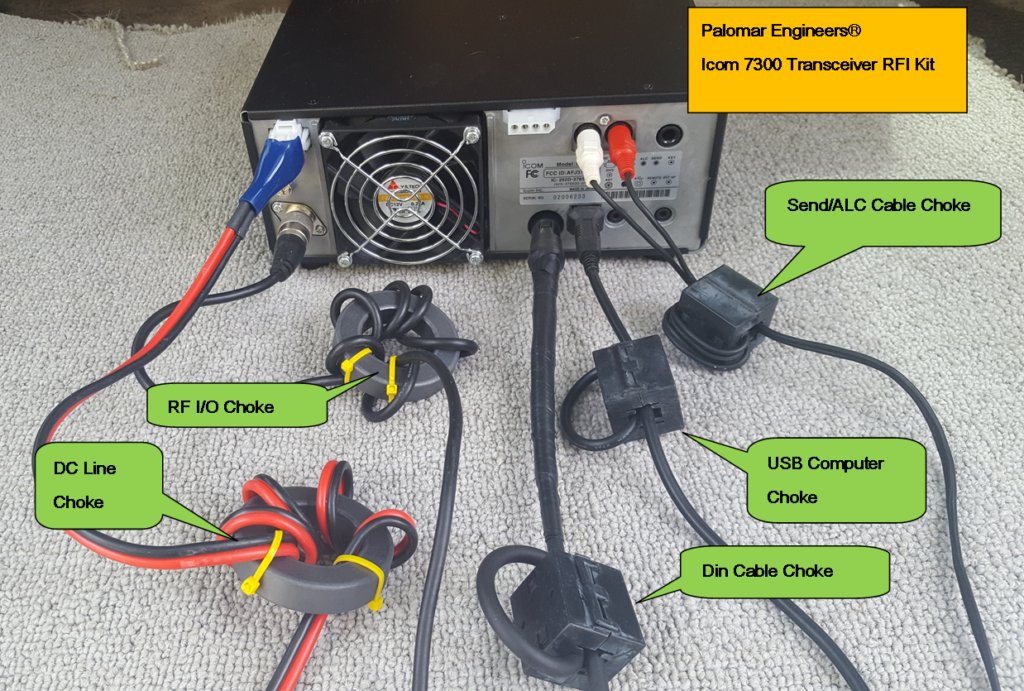
In the image above, this kit has a ferrite on EVERY cables connected to that radio. I tend to think that, in general, if you need this many RF chokes – you’re doing something wrong. It’s possible that there might be some long cables (maybe the amp or power supply is a LONG way from the radio – as in, the cable is resonant at some operating frequency. In such a case, the ferrite would de-tune the cable. Great. But in such a situation, is the antenna too close? Does the cable need to be that long? maybe. Still good questions to ask.
In the past 20+ years of operating HF, the only places I’ve generally needed ferrites have been on the power supplies to audio equipment in the station. My headphone splitter benefits from it (I think it caused feedback when I didn’t use it in one installation). In a situation where every cable has that much common mode current (enough to warrant a ferrite) – it might behoove the user to investigate their ground system a bit, to try and either improve it – or make it conductive. The energy on the shields of those cables should be flowing to ground as a log current event – or not at all.
Now – adding ferrites where they’re not needed won’t necessarily hurt anything. I’ve performed tests at sites where they had special instrumentation cables with ferrite beads every 4 inches to cut down on currents on the cable shield. But it’s extra weight, and it’s bulk in the setup that’s not helpful. I’ve also been trained at work to avoid them where possible, as some government aircraft just don’t like to have ferrites – possibly because of the possibility of them experiencing mechanical strain and shock issue, which turn them to metal dust, which causes all kinds of issues.
What about situations where your radio, as a receiver, is the victim? As an apartment dweller, I lived on the second floor, and had a simple dipole, made of 25 feet of zip cord unobtrusively stapled around the edge of my deck, with an Icom AH-4 at the feedpoint. Only one problem – my deck was directly above the air conditioners for the building – and they made HF almost unworkable when they were running. On a whim, I connected the ends of the antenna together with another length of wire, to form a squashed rectangular loop. All of a sudden, the bands were extremely quiet, and I had a very successful North American QSO Party.
What happened here? Well, the noise impeding my reception was a function of the electric field component of the energy radiating from the AC compressors. By creating a (vertically polarized) loop antenna, I impacted both the electric and magnetic fields (both exist in electromagnetics!): As far as the magnetic field is concerned, I put the A/C units, which were next to the building and below me, in the null of my antenna, which was situated flush with the edge of the building, or slightly out from the edge (it’s been over 15 years, so I’ve forgotten the exact building topology). Moreover, the magnetic field component will die off with a 1/(R squared) or 1/(R cubed) relationship – so the 20-50 foot distance provided some significant attenuation to that portion of the signal. And as far as the electric field is concerned, loops are generally immune to the electric field component of the noise – the field will impact the loop, and equally impinge onto the shield and center conductor of the coax, thus creating a common mode noise, which will essentially be ignored by the radio, since it is looking for differential mode effects within the coax as your received signal). That loop may have been a little less sensitive than my dipole could have been – but let’s face it, I was working with a compromise antenna anyway!
Now, where am I going with all this? well… the blog title is the Ramblings of yet another nerd. If you find it useful, great. if it sparks conversation, that’s good too.

