just my experience using the PAT IF buffer from SDR-KITS.COM.
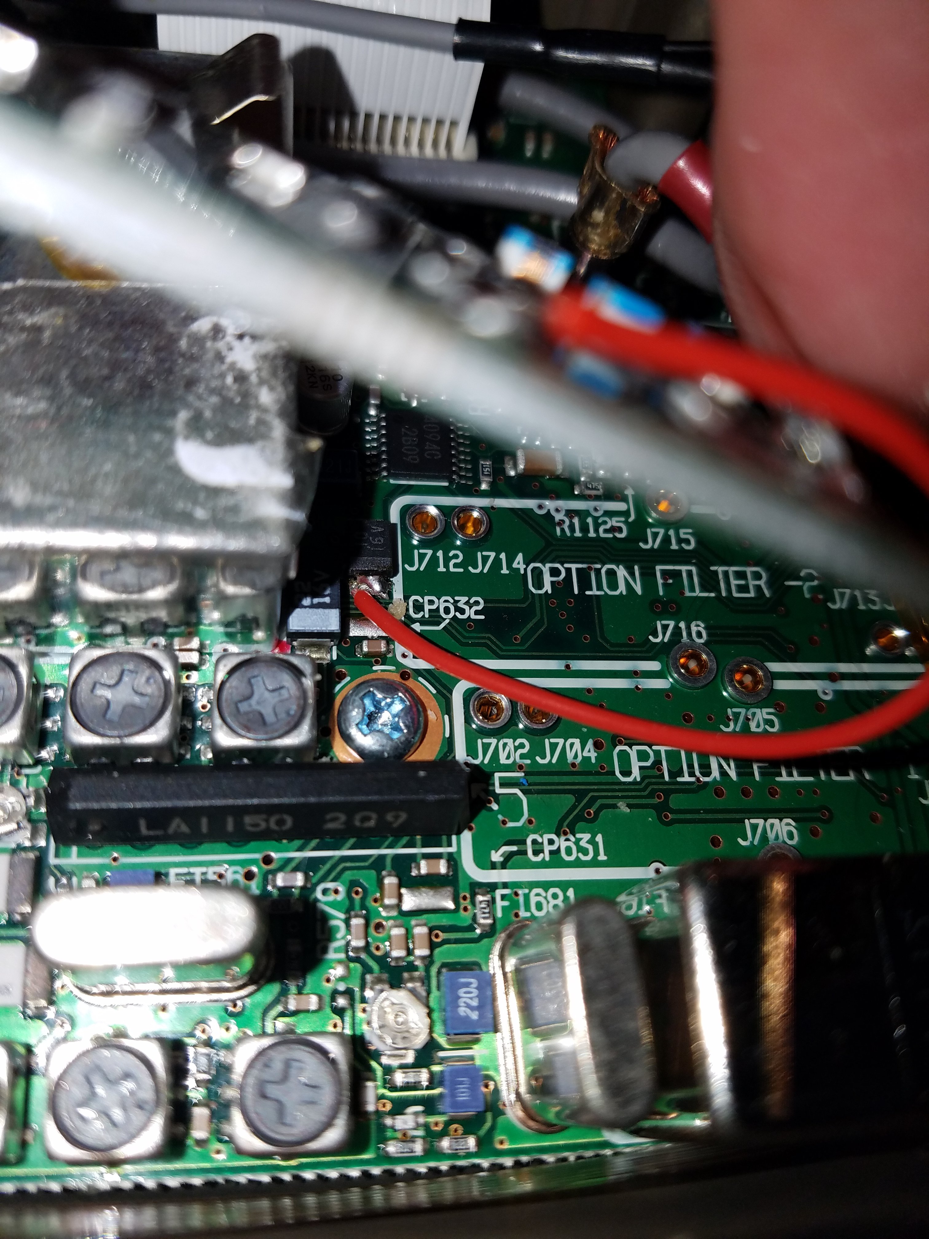
power pick off point… 7.8VDC on recieve

First IF tap point and coax connection to the PAT board.

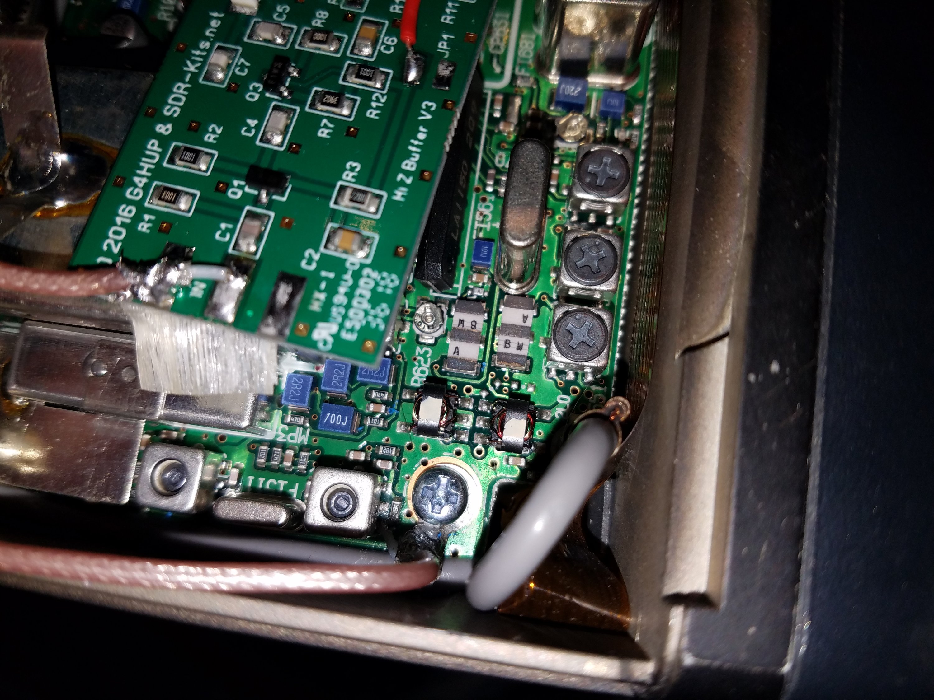
Note the shield connected to a ring terminal that goes under the closest screw to the IF connection, then the coax connects to the board in a manner which makes it fairly secure.
the output coax connects to the board in the same manner. using coax on the output is crucial to protect the output from stray RF from the transmitter and to keep the IF connected stuff from introducing noise into your receiver.
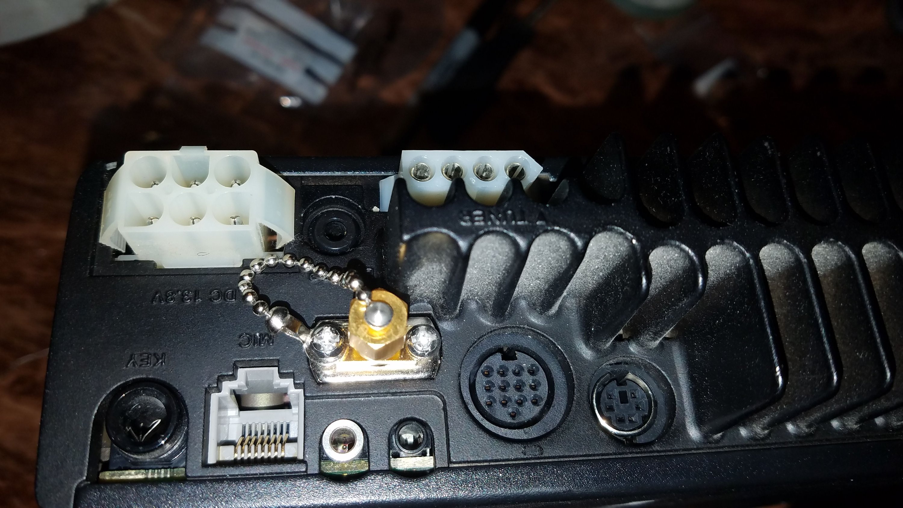
Here is the output connection. Ic9m was nice enough to plan for a connection they never implemented. I drilled the original plate as a feedthrough. because of spacing, I clipped the outer halves of the mounting ears for an SMA off. I then used some m3x12 screws (longer than the originals) to pin the sma in place.
because the SMA mounting holes were SLIGHTLY farther spaced than the plate, I started the SMA on an angle, and let the screws pull it into place securely. the cap is just to keep it clean when not in use.
