After my last post on return loss, I ended up scouring eBay for a return loss bridge – or a set of directional couplers – to measure antennas and other frequency selective devices. After this search, I was reminded just how expensive directional couplers can be – especially HP and Narda.
Fortunately, I happened across a BUNCH of Chinese produced “return loss bridge” devices, rated from ~3 MHz – 1200 or 1300 MHz. The part that caught my eye was that these devices were all selling for 20-30 dollars, with free shipping. This got me to searching to determine what these things were, since they were far less expensive, yet had a wider frequency range than the laboratory grade devices I was looking at initially.
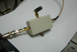
I eventually determined that these return loss bridges were simply an RF adaptation of the whetstone bridge. There were both 3-port and 4-port versions on the market – the best I could tell, the 3 port version has an internal reference load, whereas the 4 port version can have it’s reference load changed between 50 Ohms, and whatever other load one might need (75 Ohms?). If one were to try and buy a 4 port version, it is notable that many of the vendors include a 50 Ohm reference load – making it a better value.
I bought one some time ago, but haven’t had access to an RF instrument to test them out. I just happened to borrow an SDR-KITS vector network analyzer from N0AX for a while, in order to retune some cavities, which provided me an excellent opportunity to test out the return loss bridge, too.
The biggest challenge I had with the whole test was the noise floor of the SDR analyzer is a bit higher than a more expensive instrument. That being said, for the price, it’s less than half the price of a Rigol with a similar frequency range, and provides some additional functionality – in addition to making data capture a breeze, since the device is already connected to a PC.
Regardless, I tested the return loss bridge, and was happy with the results, for what they were. I have yet to compare the results to an antennalyzer or lab grade measurement, but the ability for the system to visualize VSWR performance is awesome. I ran tests on scanner antennas (small nulls at 45 MHz, 150 MHz, and a wide null at 430 MHz and a second harmonic at 860 MHz), and an 800 MHz yagi – and it was very easy to see the response of the antennas.
Admittedly, I have NOT tested the VNA’s capability as a spectrum analyzer, but I’m looking forward to testing that out in the near future.
—UPDATE—
So, I took another shot at this thing. I’m still a little unsure on how much dynamic range it REALLY has, but I wanted to test my return loss bridge with a couple antennas – and to measure a couple unknown filters. Overall, performance wasn’t too bad. Even if one only has access to a scalar analyzer (like a spectrum analyzer with a tracking generator), the return loss bridge is a very viable option.
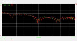
The figure below shows the results from this measurement. I found that when making some measurements, turning on some degree of averaging helps – especially when performing measurements on devices like 800 MHz cavities.
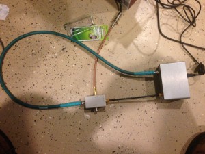
The setup I used is shown below. This test was just on a dual band larsen antenna – so I expected the peaks to be a little off-frequency.
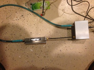
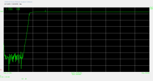
Next, I decided to characterize a filter I had sitting on a shelf because, well… I could… not to mention I’m a test equipment geek – so this kind of thing is fun! Below is the plot i captured, and a photo of the test setup
turns out the filter is a 9 MHz high pass filter – I’ll need to find a 5 MHz signal to filter out, so i can use this thing.
My only beef with the unit is the connectors. SMA connectors are great, because they’ll go up to 18 GHz (with a 40W power limit) – but they’re a hassle to mate and unmate. Since this unit only goes up to 1.3 GHz, BNC or N connectors would be far preferable. BNCs will go up to 2 GHz with no problem, and N connectors (even the cheap ones) will go up to at least 11 GHz. For this reason, I’ve actually switched over the connectors on a lot of my gear (antennalyzer, amplifiers, etc.) with N connectors. They’re also a lot easier to install, in my humble opinion.
Back to my original purpose for borrowing the VNA – the 800 MHz cavities – one of the huge benefits that this device offers is that the software will directly save an S1P or S2P file – which is a delimited ascii file that excel can import – engineers like excel almost as much as we dislike powerpoint… or as much as I dislike it, anyway…
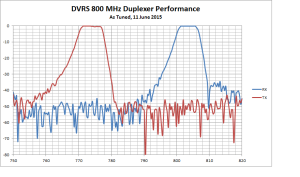
By bringing the S1P files into excel, i can easily plot both curves (TX, RX) on the same axis and see how these cans really look. I will note that this was a VERY tough process because SLIGHT adjustments at 800 MHz are quite significant, so what I got is freaking AWESOME compared to what I had. I think that I will eventually put together a primer on how to go about making some of these measurements, and some of the necessary tasks, such as calibrating out cable loss ahead of time… but for the time being, here’s what I got:
Not bad – and the best part was that we got all 4 potential repeater pairs for the state within the 3 dB bandwidth of the filters!
