I haven’t given up on my custom PCB for a soundcard interface, because it’s a labor of love…. the first board has been populated, but needs some troubleshooting. I suspect the status LEDs are giving me fits.
That being said, I had a trip lined up where I thought having a QRP HF setup would be pretty slick. Having bought a pair of Motorola XPR radios for DMR that wouldn’t program under windows 10, I worked out a deal to trade these for a Yaesu FT-817. This is not something I ever considered owning, since I already own an IC-706… but the 817 is lower power, and a bit more compact.
Once I made the deal, i started looking into accessories – no radio is complete without them. First, I started modifying my LDG AT-7000 autotuner. It won’t be seemless, but it will autotune for ANY radio at the push of a button with a slight modification.
Then I was considering what modes I wanted to operate on this trip…. voice probably wouldn’t do it, but what about digital? I’ve been looking at the Signalink USB…. they’re REALLY Close to my project, but without rig control or the USB Storage capacity. On a whim, I looked to see what other competitors existed… and this is about what I found:
- Signalink USB
- Rigblaster (West Mountain)
- MFJ
- a handful of audio isolation transformer projects using the PC’s soundcard
I’ve never been totally enamored with west mountain’s products just because the cabling was confusing. Once you got them set up, they worked great.
Signalink has a great reputation, but they’re a bit more pricey than I want to spend, and don’t offer rig control.
The misc. pile of audio isolation transformers all utilize the PC’s soundcard. This is something that I’ve said before is better avoided, because the PCs soundcard will, by default, put windows system noises on the air… and not all laptops have appropriate connections for this type of setup.
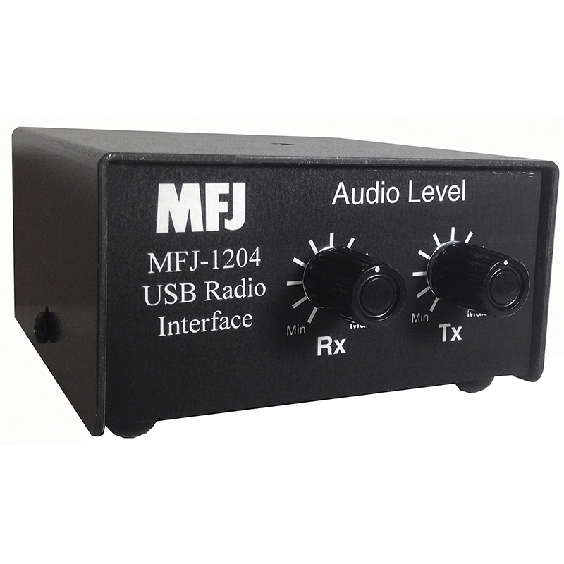
This leaves the MFJ…. by all accounts, it’s similar in size to my PCB, and looks like a copy of the signalink functionality. Honestly, the MFJ construction is in some ways comical…. rather than employ a USB type B connector in the chassis, they have a USB soundcard in the box, and use a USB extension cable fed through a slot in the case…. then again, it’s a way to control costs.


So… I found an MFJ1204 wired for a 13 Pin DIN Icom radio for 70 bucks on Ebay, and bought it. If nothing else, it’s set up for my IC706 out of the box.
When I looked at the product, I noticed that the jumper connectors are just moving fixed signals around on the output connector (An RJ45). In most cases, all possible signals on the left side of the jumper are not used, leaving open spots on the right side. One jumper configuration setup is shown below (from the MFJ manual)

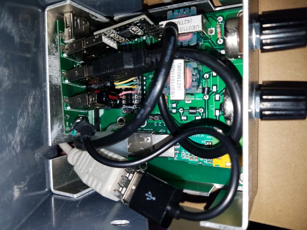
Note there is a lot of space in the case… I happened to have a small USB hub, USB portsaver (6″ extension cable), and USB to TTL serial converter on a shelf. With a little effort, I got all of them into the box. (note – the image below is proving they will fit, the final product is cleaner). Part of the fit was to remove the plastic housing from the USB hub, and use foam double stick tape to secure it to the inside of the chassis.

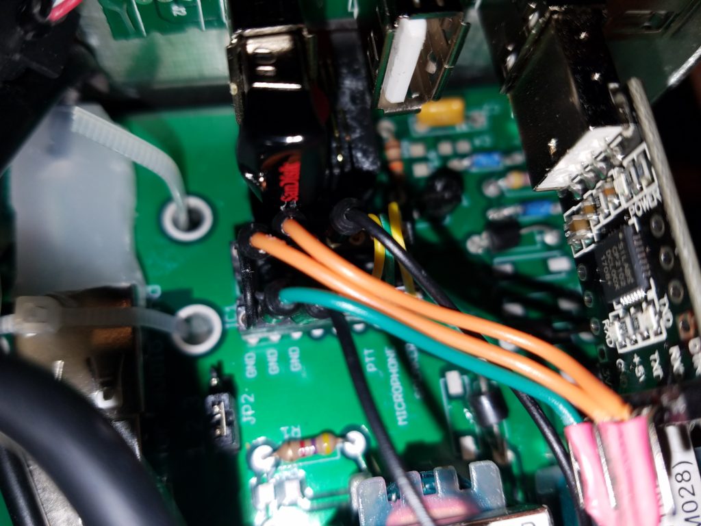
Then I needed to get signals out… note that pins 4, 6, and 7 are unwired. I made the following connections:
- Right Side Pin 4 is wired to a Left Side ground pin
- USB to TTL Serial ground is connected to one of the left side ground connection (fed in with a wire jumper soldered to the USB to Serial adapter)
- USB to TTL Serial RXD is connected to Right Side Pin 6 (fed in with a wire jumper soldered to the USB to Serial adapter)
- USB to TTL Serial TXD is connected to Left Side Pin 6 (fed in with a wire jumper soldered to the USB to Serial adapter)
- Splice DTR (serial pin 4) to the PTT jumper in the jumper plug. This allows the computer to positively key the radio through the serial port.

This means I now have the full functionality that I had planned for… I just need to build a cable. Below is my schematic (using an Ethernet cable as my basis to build a Y cable for the FT-817 to provide both CAT control, as well as digital mode operation).

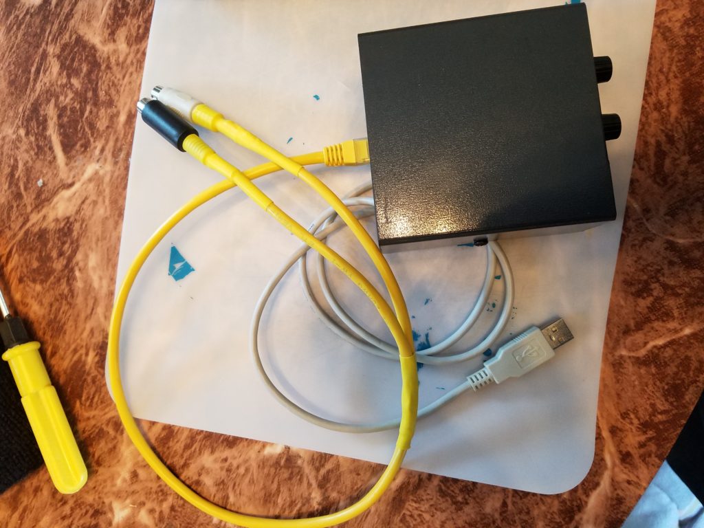
with a little solder and heatshrink, here’s the cable I fabbed up for my FT-817, which includes CAT functionality as well as the audio interface. I connected it up, and it almost worked perfectly. I had a bad USB to TTL converter, which I replaced, and had the RXD and TXD lines swapped. all easy fixes!

All that said – below is a file showing all the different cables I’ve considered. I will be adding an FT-1000 cable to the mix. Note that I’ve added a “ver 2” mod and cable set which is NOT compatible with version 1. Rather than add a second ground pin in the output connector, I pulled both the DSR and RTS lines from the serial adapter into the connector, and just branched the ground connection. The reason behind this is then the RTS can be used to key the radio for CW, thus taking advantage of all the possible modes of operation I can think of at the moment.
Once I return from my trip, I’ll end up retrofitting my cable into a ver 2 cable, and adding the extra line to the output connector, effectively making my 1204 the “ver 2” mod shown in the PDF. I did throw some snapshots of connector pinouts form radios in question into the end of the file – those belong to the respective manufacturers!
