Many life changes have resulted in a change of shack configuration. I’ve also acquired an Icom 706 again (thanks, Lou). In tinkering, and deciding how I want to operate, I decided that I’d like to have the ability to do “soundcard” digital modes with the 706 either while portable, or just at the dining room table. Going back to my recent post, I looked through the configuration, and noted that I could easily develop a similar unit tailored to the 706.
In all reality, I could take my original design, and build a new cable off the DB25 connector I used – but rig control would be one major difference – the Yaesu version (we’ll call it Ver 1.0) included a USB to serial connection for rig control – so additional adapters would have been required for the Icom, which uses a single bi-directional TTL bus (CI-V). While most adaptors for CI-V simply tie TX and RX together, I found http://nerdralph.blogspot.com/2014/01/avr-half-duplex-software-uart.html in which the author had developed a single transistor isolation scheme for TTL RX and TX lines. Previously, I had used a 4 FET solution, but this version was a bit simpler, so I decided to include it in the design.
Additionally, the Icom has TWO PTT lines (one for HF, one for UHF/VHF). Since I didn’t see any reason to put two drivers in the system, I decided I would simply put a switch in the cable (my original cable omitted the VSEND line, since I was only interested in HF operation) to toggle between the available PTT lines on the radio, if needed.
My original version used a DB25 connector for radio interface, which has LOTS of spare pins, but this version needed to be smaller (why go with a huge connector, when the RADIO is small?). By selecting parts a bit more carefully, I found that I could shrink the overall package a fair bit – but I still wanted to have some “extra” pins available for growth, so I shrunk the connector down to a DB15. (some options include things like radio tune control or band data decoding for amplifiers).
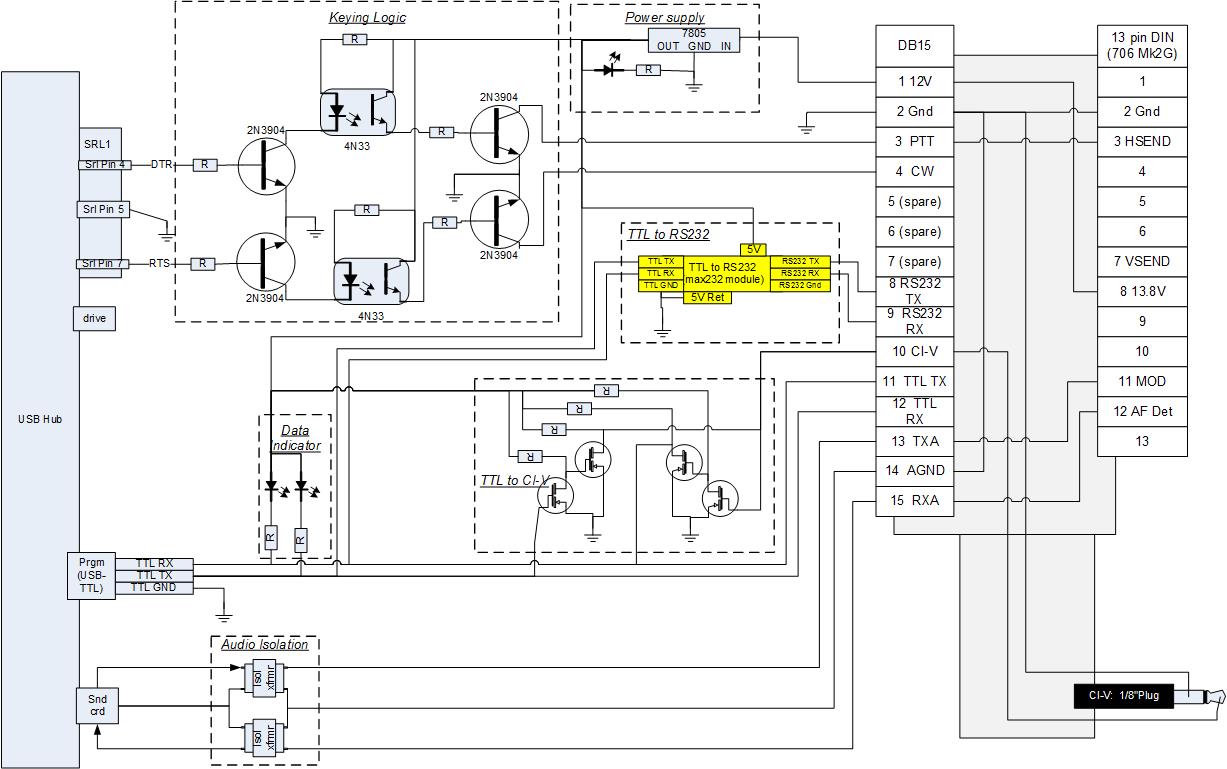
One feature that might be noticed is the separate ground feed from the output of the isolation transformers. I supplied this isolated (separate) audio ground for applications where ground loops could be present, and the radio might allow for an isolated audio ground (some higher end radios provide this, as well as some commercial radios, such as Motorola Spectra and Astro mobiles).
In reviewing my original plan (Icom 706 ONLY), I had the TTL lines combined within the unit – which seems to be the accepted convention for using a USB or RS232 to TTL converter for CI-V. The issue this posed was that I wouldn’t be able to do ANYTHING differently in the future (such as Yaesu, Vertex, Kenwood… anything non-ICOM)… so I add a TTL to CIV converter inside the unit, using the TTL combination circuitry from my previous post on USB to TTL conversion for radio programming at https://www.kc9umr.com/?p=30 . In addition, I brought both the separate TTL and combined TTL connections out of the unit on the connector – which will be less restrictive for future applications. While I was at it, I put a MAX232 board inside the unit, and also brought my RS232 TX and RX connections to the connector – so the overall design is more universal, allowing me to build different breakout cables as necessary.
The Max232 required 3-5VDC, so I thought it would be a good idea to put a 5V regulator inside the unit.
http://www.ka1mda.org/ham/homebrew/civ/index.htm Gave me a great idea – since I put a 7805 in the design for the RS232 converter, I could easily use a pair of LEDs to indicate data transfer by simply tying them to the 5V rail through a resistor. This would not indicate RS232 specifically, but since it would be connected to the primary TTL interface, it would work just fine to indicate ANY data transfer.
Since I was including the 5V regulator on this version ANYWAY, I decided that there was no reason to run 12V to the optocouplers for the keying circuitry – therefore, I changed these to 5V operation, as well. At the same time, I added an LED to the 5V output to simply indicate that the system was connected and receiving sufficient voltage to power the 5V regulator.
Note: “Version 1” was my original Yaesu configuration: https://www.kc9umr.com/?p=91 “Version 2” was my Vertex 1700 configuration: https://www.kc9umr.com/?p=125
I believe this version would work just fine for the VX1700 application, using only a different radio interface cable, which would short the DCD and Ground pins in the DATA jack, and then, of course, connecting to the appropriate connectors.
The final schematic is shown below. Note that at this time, this is a design only – I have ordered parts to build one, so there may be “lessons learned” updates to follow. I added some sectioning to delineate functions of some of the circuitry that has to be added via a small PCB in the unit, as opposed to the COTS (Commercial Off The Shelf) parts that will simply be wired together.
Everything to the right of the DB15 is “Icom 706 Specific” – the concept is that the specific radio interface cable determines what the system is configured for – there should be little to no modification of the unit necessary to change radios. The TTL to RS232 converter is in yellow, as it’s completely optional for my current application (Icom 706). I have ordered the Max232 converter, so it will likely be included in my first actual build.

